Online Protractor Accuracy: Calculation, Error Sources, and a Repeatable Check
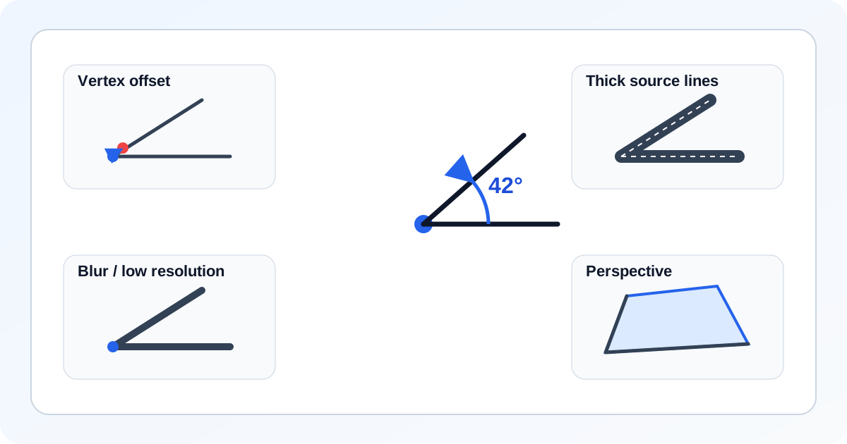
An online protractor can calculate the angle between two rays very consistently, but that does not mean every photograph, scan, or screenshot contains an equally trustworthy angle. The calculation and the source image are two different parts of the measurement.
This guide explains what Online Protractor calculates, what it cannot know about an image, and how to repeat a measurement so the result is useful rather than merely detailed.
What the Tool Actually Measures
Each ray has the protractor center as its start point and a user-placed endpoint. The direction of a ray is calculated from the horizontal and vertical difference between those two points. The tool uses the same relationship represented by JavaScript's Math.atan2(y, x) function, then converts the difference between two ray directions into degrees or radians.
That calculation answers a narrow question:
What is the angular difference between the two directions I placed on this canvas?
It does not automatically answer whether the uploaded photograph preserves the physical angle of the original object. Perspective, lens distortion, a bent sheet of paper, or an incorrectly stretched image can change the angle visible on screen before the tool begins calculating.
Display Resolution Is Not Measurement Accuracy
Online Protractor can display zero to four decimal places. Those digits describe display resolution. They do not promise that a photographed corner is known to 0.0001°.
For example, a clean synthetic diagram may contain two mathematically exact rays at 0° and 42°. If the endpoints are placed on those lines, the calculation should display approximately 42°, subject to the chosen display setting. On a blurry phone photograph, however, the visible edge may cover several pixels. Different reasonable placements can produce slightly different readings even though the software performs the calculation correctly each time.
A Reproducible Geometry Check
You can separate calculation behavior from image quality with a simple controlled check:
- Create or use a clean diagram with a clearly marked vertex.
- Draw one reference ray horizontally to the right.
- Draw a second ray at a known value such as
30°,45°, or90°. - Upload the diagram without stretching it.
- Place the protractor center on the marked vertex.
- Place one measurement ray along each source line.
- Repeat after clearing or moving the rays.
| Reference diagram | Expected relationship | What the check demonstrates |
|---|---|---|
| 30° | Acute angle | Basic ray direction and degree conversion |
| 45° | Half of a right angle | Repeated endpoint placement |
| 90° | Perpendicular rays | Center alignment and a familiar sanity check |
This check does not calibrate your monitor or turn the browser into certified metrology equipment. It verifies that your placement workflow and the visible diagram agree on a known geometric relationship.
The Four Main Error Sources
1. The Center Is Not on the Vertex
Center placement is usually the most important manual step. If the protractor center is offset, the two measurement rays no longer represent the original sides from their common endpoint.
Zoom in before placing the center. If the vertex is hidden by thick lines, estimate the intersection of the two line centerlines rather than choosing a convenient outer edge.
2. The Source Lines Are Thick or Blurry
A ten-pixel-wide line does not provide one obvious endpoint path. Choose a consistent convention—normally the visual center of each line—and use the same convention on both sides.
At a ray length of about 200 screen pixels, a two-pixel sideways placement difference corresponds to roughly atan(2 / 200), or about 0.57°. This is an illustration of sensitivity, not a guaranteed error bound: the direction and location of the offset matter.
3. The Image Was Stretched
Uniformly enlarging or shrinking a clean image preserves its angles. Stretching width and height by different amounts does not. Avoid browser previews, document exports, or image editors that squeeze one dimension independently.
4. The Camera Introduced Perspective
A photograph taken at an angle shows a projection of the object, not necessarily its true face-on geometry. A physical right angle can look acute or obtuse when the camera is not parallel to the measured plane.
For physical work, photograph the surface as square-on as possible and treat the online result as a preliminary visual check. Verify fabrication, inspection, safety, or contractual decisions against the object or an appropriate calibrated method.
Worked Example: Checking a PDF Screenshot
Suppose a PDF screenshot contains a corner that appears close to 42°.
- Crop the screenshot around the corner while keeping both sides long enough to follow.
- Open the Online Protractor and upload the screenshot.
- Place the center at the intersection of the two line centerlines.
- Select Measure Angle or press
M. - Place the first ray along the lower reference line and the second along the sloping line.
- Record the result, clear or reposition the rays, and measure again.
- If repeated placements vary—for example,
41.6°,42.0°, and42.4°—report a sensible rounded result such as “about42°” instead of presenting the longest decimal value as certainty.
For a complete document workflow, continue with how to measure angles in PDF drawings.
Which Features Affect the Reading?
The Free plan includes one image, one protractor, ray measurement, manual JSON backup, and 1x PNG export. That is enough for the controlled check above.
Plus and Pro add multiple objects, snapping, grid and ruler overlays, CSV, JPEG, overlay-only, 2x/4x image export, and automatic recovery of the latest local workspace. Pro additionally adds named local projects and PDF reports. These features can improve workflow and documentation, but they do not remove errors already present in the source image.
Snapping deserves special care: it is useful when constructing or checking an expected standard angle, but it can force an irregular angle toward a preset value. Disable snapping when you want to observe the source as it appears.
A Practical Reporting Rule
Match the reported precision to the evidence:
- Clean synthetic diagram with repeatable placement: report the stable displayed value.
- Clear screenshot with narrow lines: one decimal place may be useful if repeat measurements agree.
- Blurry scan or perspective photograph: use a rounded estimate and describe the limitation.
- Safety-critical or professional decision: use an appropriate physical or calibrated method as the authority.
The most credible result is not always the one with the most digits. It is the one that another person can reproduce and understand.
Final Checklist
Before exporting a result, confirm that:
- the image was not stretched unevenly;
- the protractor center is on the actual vertex;
- both rays follow a consistent part of each source line;
- snapping is appropriate for the task;
- a second placement gives a similar answer;
- the reported number is rounded to match the source quality; and
- important physical decisions are verified outside the screenshot.
For additional practice, compare this method with estimating angles without tools and review angle types and classifications.
Sources and references
- Math.atan2() — MDN Web Docs
- SP 330 — Plane angles, solid angles and phase angles — National Institute of Standards and Technology
- Grids, guides, and measurements in PDFs — Adobe Acrobat Help
Ready to measure angles?
Try our free online protractor tool right now. No download required.
Use Online Protractor